


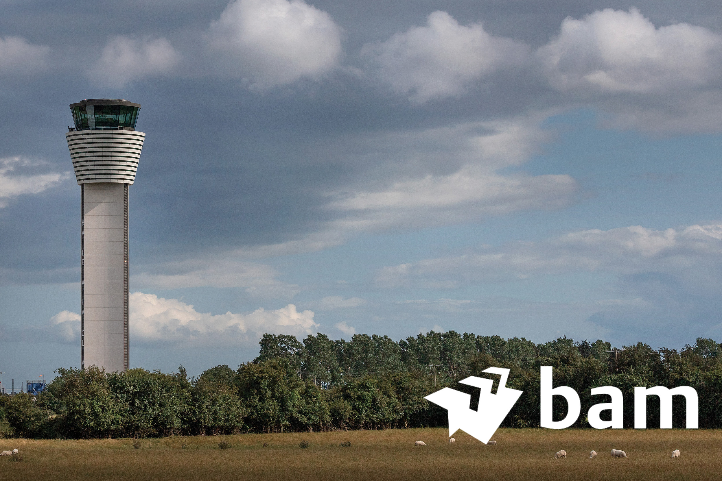
The location of the Visual Control Tower (VCT) building is within the demesne of the current air traffic control facilities at Dublin Airport.
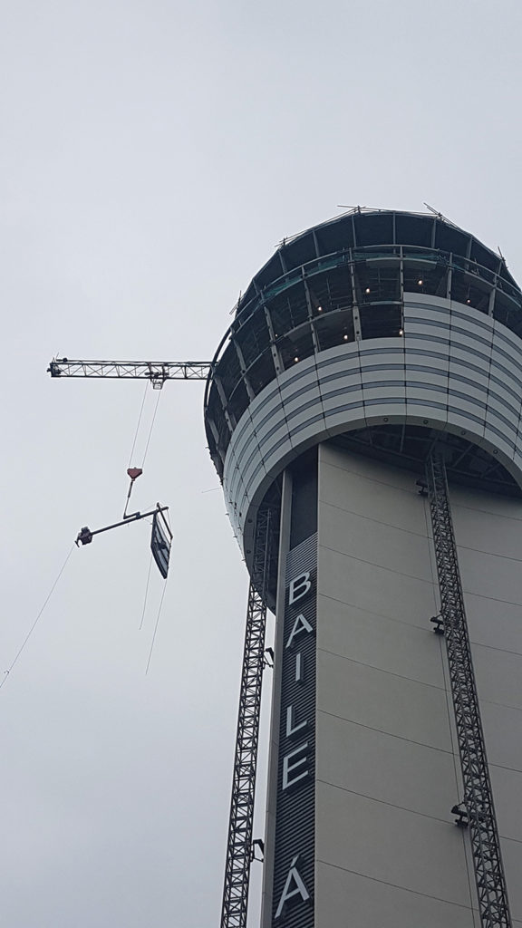
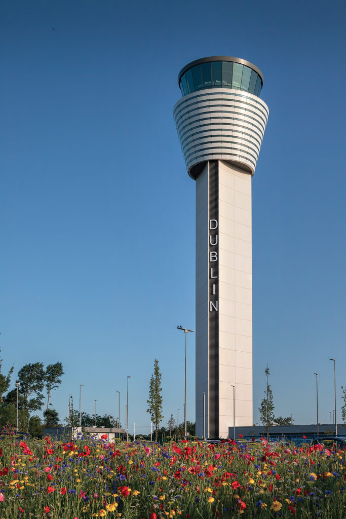
The height of the new elegant and modern structure has become a significant feature on the Dublin skyline. It is identifiable by the professionalism of the IAA as the Client and the Main Contractor, BAM, along with the wider design team. The new Control Tower Building is a worthy symbol for Dublin, Ireland’s gateway city. The construction of this control tower is the keystone to the ambitious ongoing and future expansion of Dublin Airport. As Ireland’s primary airport, Dublin is in pole position to continue to increase its year on year passenger numbers and to expand passenger routes options for leisure and business passengers to and from the island of Ireland. Dublin ‘baile atha cliath’ is well on its way to becoming one of the most connected destinations in the world. This new control tower is essential to its continued success. The benefits and the future opportunities the tower provides will be felt within the local community, countrywide and among the traveling passengers worldwide.
The new Dublin VCT comprises three separate but integrated building elements:
• A control cab and associated elements.
• The cab supporting shaft.
• A base building. The base building will accommodate staff facilities, electronic systems and mechanical plant space to provide control of the building environment.
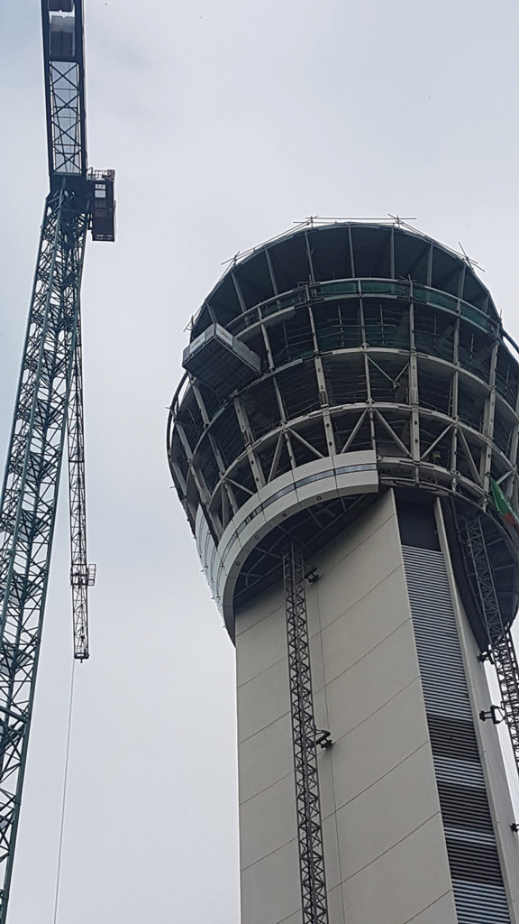
Now the tallest occupied building on the island of Ireland at 86.9m, the overall height of the VCT structure resulted from the operational requirement for a control room floor level of 80m above ground level. In order to provide a slim, elegant structure and in an effort to keep the tower as light and elegant as possible, most of the support accommodation (technical rooms and associated plant) has been separated from the Tower and is located in a single storey support facility at ground level. This support building is connected to the Cab Shaft with a fully glazed single storey link corridor. The separation of the tower and support accommodation ensures that the free-standing quality of the tower is unaffected and consequently the new facility appears as two distinct elements, each containing their own distinct functions.
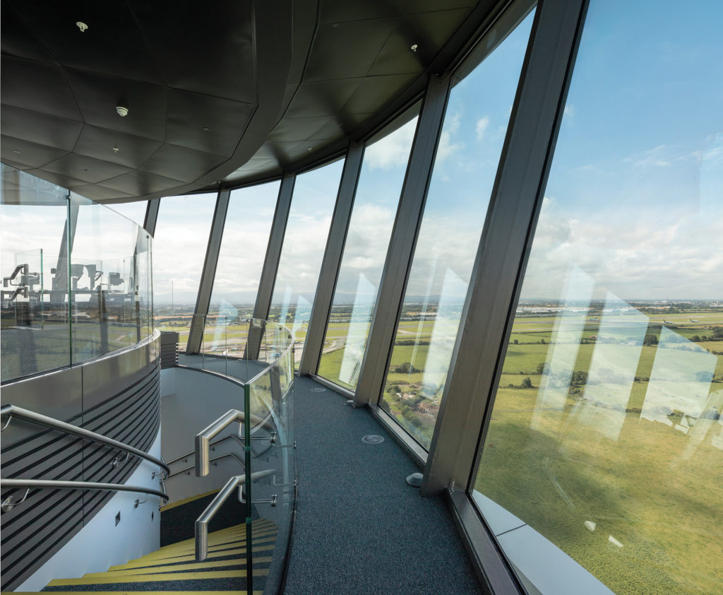
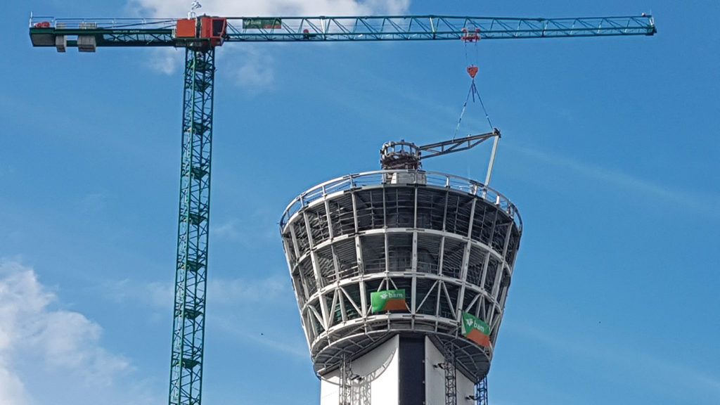
The cab structure itself comprises of five levels and contains essential technical facilities / staff accommodation, plant space, technical equipment, maintenance facilities and the Visual Control Room (VCR) itself. The tapering cone shape of the cab is a result of the spatial requirements of the various functions at each level, and their relationship in terms of proximity to the VCR. The support shaft to the cab is an essential element of the structure. A considerable design feature was to make it as slender and unobtrusive as possible. Its triangular plan form derives from the three modes of vertical circulation from bottom to top: the two lifts and the single escape stairway.
Dublin’s Visual Control Tower – A concrete, steel and glass engineering masterpiece
Winner of the Engineering Project of the year at the Irish Building and Design Awards 2019, the VCT project had three critical engineering challenges. These would ultimately determine the success of the project. The concrete works are the main component of the structure and of critical importance. In addition to this, the concrete works were substantially exposed and thus are a significant architectural feature of the building, both internally and externally. The structural steel frame of the cab area of the building cantilevering from the concrete stem provided several challenges including extremely tight construction tolerances to receive direct fixing of the glass without a separate glass framing system, access challenges at 70m to 90m above the ground and a negative incline to the building with an increasing cantilever as one moves upwards. This required a unique level of ingenuity and collaboration to ensure the design, particularly connection details, was in sync with the construction sequence and access methodologies. This was critical to ensure the safety of our operatives was not compromised. The façade and the glazing to the cab area had two distinct facade types aptly named “Type 1” and “Type 2”. Again, due to the unique nature of the building, the façade used on the cab of the VCT did not exist as a certified façade system. BAM, along with our partners, developed a new façade system, which needed to be put through a full suite of CE certification tests in an extraordinarily short period of time. BAM’s buying power in the market combined with the expertise and relentless drive, made this happen on time to meet the needs of the project timelines. Similarly, detailing of this unique façade system was tailored to match the steel and façade installation sequence and access provisions for operatives and inspectors. Most of the engineering works on the control tower building was completed at a desk or around a meeting room table to ensure works on site were safe, swift and accurate.
Concrete
The Visual Control tower project at Dublin Airport included many different concrete components, which required several different construction approaches needing ingenuity, detailed planning and proactive collaboration between the main contractor and several different subcontractors and designers. Through collaborative team building among the various stakeholders, with decisiveness and clear direction by BAM, the successful completion of all concrete works on the Visual Control Tower was achieved in October 2018. There are three distinctive concrete aspects of this project.
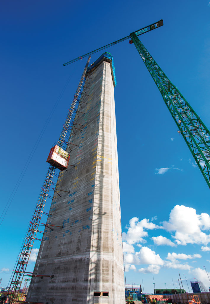
Slipform
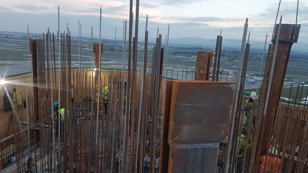
With two different configurations on plan with adjustments completed without stoppage, the slipform construction of the stem or shaft of the tower was the single most critical aspect of the VCT project, which required detailed planning and collaboration. Key early decisions included the type of slipform rig to be used based on site conditions, speed required and concrete transport methodology. Following this, detailed collaboration was required between many parties to guarantee the success of the slip. These parties included; the concrete supplier/mix designer, the reinforcement supplier, the structural engineer, the steel fixer and the slipform subcontractor.
Other influencers included the decorative white concrete panel contractor, the structural steel contractor/designer, lift suppliers, builders hoist provider, precast stairs suppliers/designers, the M&E subcontractors and the architect. Within this context, the slip itself was a substantial coordination task prior to commencement of the pour. Ultimately, this pre-planning and early coordination led to the slip being a massive success with finishing of exposed internal walls progressing as the tower climbed and to the heights of standards. This, combined with pouring concrete in temperatures as low as -4°c, proved to be significantly challenging, which were overcome through collaboration and the use of best practice guidelines for concreting in cold weather. Other key factors contributing to the success for the slipform included; the positioning of the tower crane and concrete loading points in line with the prevailing winds for Dublin Airport to ensure minimal downtime and the comprehensive testing of mix designs and their respective open times to ensure climb pace could be adjusted as required.
Interesting Slipform Facts
Slipform height: 81.2m
Slipform Start date: 12th February, 2018
Status red weather alert: 5 day stoppage due to storm Emma (28/02/2018 – 05/03/2018)
Slipform completed: 9th March, 2018
Total days slipforming: 20 days
Average climb rate / 24hr: 4m
Fastest climb rate / 24hr: 5.5m
Total tonnage of reinforcement: 335 tonne
Total cubic meters of concrete: 1686m³
Total tonnage of embedded structural steel members: 17 tonne
Total cast in components for hanging precast façade panels: 456no.
Total cast in components for structural corbel reinforcement: 640no.
Total linear meters of conibar: 622 linear meters
Cast in electrical conduit: 182m
Cast in electrical outlets: 72no.
Concrete Corbel at 70 meters above ground
During detailed reinforcement design, it became clear that a standard corbel design would not be adequate to support the loads from the steel cab structure and transfer them into the load bearing RC shaft. The three points of the triangular shape of the tower caused a significant design issue wherein a traditional corbel could not provide enough load paths back to the RC support columns within the RC walls. From an engineering perspective, this posed a substantial challenge, which required significant thought and ingenuity. It was decided to combine a traditional corbel on the longer elevations of the six-sided shaft with cantilever transfer beams that wrapped around the three shorter elevations or peaks of the triangular shape of the tower building. This unique concept provided an optimal load path to transfer the cab loads safely back to columns constructed within the RC walls.
While this resourceful concept was adequate and possible in theory, the detailing of the reinforcement still posed a significant challenge and required several passes on the collaborative design table hosted by the BAM. This process brought the design to a final detail with a level of satisfaction that it could physically be built though reinforcement congestion and physical ability to torque 640no. 16mm and 25mm couplers remained a concern prior to construction.
During construction, the unique nature of the reinforcement detail posed many challenges including; rebar installation sequence, workability of the bars and the existence of tools on the market suitable to install and torque the reinforcement on the position couplers. The contractor designed and manufactured new bespoke tools for the construction of this corbel and in tandem with skilled operatives this led to the successful completion of the corbel.
With a unique reinforcement design of this nature and working conditions 70m above the ground, there was also a further complication in that the formwork needed to be hung from above due the presence of the finished white concrete panels below over which the corbel sat. The construction of this 700mm wide by 800mm deep RC corbel proved to be an extraordinary piece of engineering and workmanship. This was achieved through careful planning and proactive collaboration with formwork contractor, the steel fixer, the reinforcement and coupler supplier, the temporary works and formwork designer, the permanent works structural engineer and BAM as the main contractor as the primary focal point and engineering lead.
Architectural white concrete precast panels
Installed before the corbel to facilitate crane access, the curved white concrete precast cladding panels formed a key architectural feature of the building. Attention to detail was the key component in ensuring the desired high-quality finish could be achieved, while balancing this with time constraints and the construction of the remainder of the tower. These panels had to be completed prior to the corbel above due to the geometry of the two components and the required sequential installation of the panels themselves.
Early detailed design of the panels was completed in order to permit the integration of the 456 cast in fixing components into the slip-formed concrete core to both hang the panels and to laterally restrain the panels. The installation tolerances for these cast in components was +/- 10mm.
The curved profile of the panels proved to be a significant challenge in the workshop. Early design permitted 114 panels to be manufactured using only two moulds, which were repeatedly re-used and thus provided absolute consistency in the panels. These moulds were modified for the ten slightly different panel shapes required. This manufacturing consistency and accuracy in the process proved critical during the installation phase, ensuring no unplanned stoppages were required during the installation.
Strong winds proved to be a significant threat during the installation process, due to the exposed nature of the airport site, the height of the works above ground and the large surface area of the panels. Using only the tower crane for installation, “wind windows” needed to be utilised with efficiency as no supplementary time was available for any unplanned events. Using highly skilled operatives and a detailed lift plan, works proceeded swiftly with an average of 10 panels installed per day when suitable wind conditions permitted.
Access for the installation was a challenge that needed to be considered carefully during the design of the panels and more specifically, the panel joints and fixing locations of the panels. Traditional temporary tie joints were not an option for the proposed mast climbers to ensure no patches were required in the panels (due to the ties). To overcome this, it was decided to build the mast climbers in tandem with the panels by altering crews on the three available work faces. This permitted the installation of the specifically designed ties through the joints of the panels. Using a bespoke hockey stick design, these mast climber ties were later easily removed without any impact in the panel leaving a sacrificial galvanised anchor plate inside the cavity. This approach proved extremely successful and efficient and contributed significantly to the high standard of finish achieved in the installed panels.
Other key concrete features of the Visual Control Tower Building
• 2.25m thick 600m³ RC foundation on 36no. 900mm rotary board piles up to 25mm deep inside an 8m deep excavation.
• Construction of a single storey RC building over a single storey basement. This building is connected to the tower via a link bridge corridor included ground bearing slabs with anti-flotation anchor piles, RC walls, RC flat slabs and concrete blockwork walls.
• RC boundary anti-burrow security wall with integrated fence.
• Installation of 22 storeys of precast concrete stairs with in-situ landings.
• Construction of a radial concrete feature stairs to the top floor of the building.
• Pouring of the cab floors and roof on metal deck with cab 1 at 70m above ground level.
• Pouring of flat slab floor to the top floor of the building 80m above ground level with unique temporary works in place.
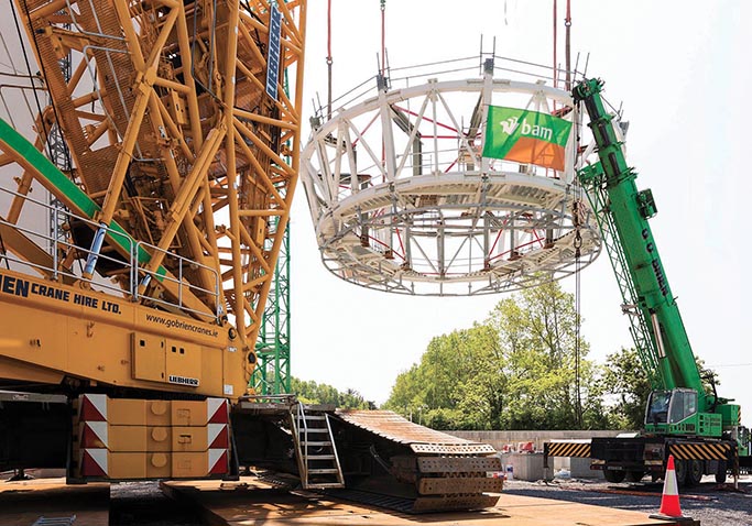
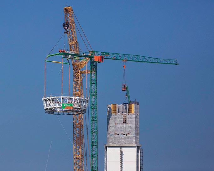
The Steel Cab
The construction of the steel cab commenced at the design desk. In order to successfully coordinate the construction methodology with a design that would facilitate safe and accurate construction, BAM assumed full control over the design approach. There were several potential methodologies to construct this cab, all of which were reviewed with regard to several key factors, most notably, safety during construction, the control of quality, costs and the impact of the steel design on other key components such as the concrete works and façade works. Using this approach, it was ultimately decided to fully embed 12 steel columns into the slip-formed shaft with flat plate connections to weld the steel into place. Though a permanent structural component as part of a multi
Type 1 to the upper cone
The accuracy of the steel installation was of critical importance for the installation of the Type 1 glass as these structural steel members had the dual purpose of also being the mullions for the control room glass. As visual clarity was of upmost importance for the air traffic controllers, the glass was specified to be annealed to eliminate the slight imperfections that would be induced by the heat strengthening process of due to the type of glass chosen. This meant that the installation crew not only had to battle strong winds and work within tight wind windows when it was safe to do so, demanding access conditions from Star 10 MEWP’s, 5m tall and 1100kg glass DGU’s to a 14° negative incline, they also had to install the most fragile type of glass to millimetre accuracy. The planning of these works could only aid to a certain point. The skill of the operatives, site engineers and crane driver were the key drivers to the successful completion of this aspect of the project.
Safety, Cost and Schedule Control
The safety of site personnel and end users, combined with the need to deliver a high-quality product, may be the key components to the success of a project. However, success in these areas can be overshadowed if costs and time delivery targets are not met. Control of costs are essential to ensuring the sustainability of a business and the industry. The control of project timelines has a direct impact on costs for contractors and clients alike. Project success can only be obtained through successful control of all four criteria; Safety, Quality, Costs, Timelines. Without this, success is not truly achieved. This project focused on costs through the control of the other three criteria, all of which have an impact on costs either directly or indirectly. As a project with a high-risk profile, safety was managed on an hourly basis and through the implementation of BAM accredited Safety Management Systems. Similarly, the quality of the works was closely monitored both on and off site. As these two areas were incident free, unexpected costs were minimal and thus became easy to manage. In its purest sense, costs were controlled through good management of cashflow and monitoring of forecasted spending against agreed income. Each month, the projects financial prognosis was updated and assessed on a package by package basis and risk funds were closely monitored. Timelines were tracked on a weekly basis and communication with our supply chain was kept live to ensure they had optimum ability to adapt to the projects needs as works progressed. Due to the nature of the project, flexibility within our supply chain was a key component outlined to each subcontractor before a subcontract was awarded. This provided the ability to ensure workflows were seamless and productivity was high. Close communications between contractor and client was another successful aspect of this project. Built on honest communications, adjustments to the works were maturely communicated and discussed in a timely manner. This provided the basis for swift financial agreements on works adjustments, equipping the contractor and client with a platform to progress, reducing exposure to risk and the ability of manage project finances with a high level of accuracy. These measures combined ultimately ensured the project was delivered to the client on schedule and on budget.
The Author
Tadhg Kelly joined BAM in 2007 as a recently graduated engineer. Throughout his career he has gained experience across several sectors as a key role-player within multidisciplinary project teams. Tadhg is currently a Senior Contracts Manager for BAM on the New Children’s Hospital project overseeing the internal fitout works of this world class hospital facility.
Tadhg managed all aspects of the construction and many aspects of the design development of the new VCT Building, from tender stage of the project through to its completion in Q1 2019. As a qualified structural engineer, Tadhg was able to combine his technical knowledge with his management experience and his keen focus on meticulous planning and the harnessing of a proactive team environment as the key components in the successful delivery of the project.